Generalized Parameter Extraction Method
INTRODUCTION
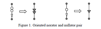
Each of the symbolic analysis method can be classified to the group of algebraic or topological methods [1], [2]. All approaches have certain advantages and limitations. But possibly one of the most common points among them is that the first stage of analysis requires a special presentation of the network as a number of algebraic sets or topological graphs. In this paper a method that doesn’t need any intermediate and preparatory stages is proposed. It is based on special transformations of the analyzed network and a presentation of active elements (controlled sources) as oriented nullator and norator pairs. This concept develops the singular elements approach discussed by A.Davies, J.Braun, M.E.Parten and R.H.Seacat in [3], [4], [5] where the oriented nullors have been used, and generalizes the determinant expansion formulas firstly proposed by W.Feussner in [6], [7] (see also papers [8], [9], [10]) for passive circuits. Fig.1 indicates the modified nullor. The orientation of the nullator and norator corresponds to arrows shown as triangles instead of standard ovals.
Formally the method belongs to the class of algebraic methods, because the result in a general case is presented as determinant expansion (parameter extraction) equations. All types of controlled sources can be included to the consideration. In opposite to the presentations of controlled sources proposed in [11] no extra elements are needed. The calculation consists of a number of formalized operations with external
nodes those of them are connected to the elements using for the determinant expansion (parameter
extraction). The main advantage of the method is that there are not any cancellations among the generated
terms. From this point of view, possibly, only the twograph method (and its modification, for example
discussed in [12], [13]) has got the same efficiency. But the active elements presentations in the two-graph
method are more difficult than proposed in the current paper.
The paper is organized as follows: after the short Introduction main theoretical basics of the proposed algorithm are considered in the Section 2. Practical example is discussed in the Sections 3. Conclusion summarizes the paper.
DESCRIPTION OF THE METHOD
To understand the proposed method we’d like to consider shortly the algorithm presented in [4], [5]. These authors has considered the circuit containing a number of passive elements and oriented nullors. For calculation of the determinants the Feussner's formulas have been used
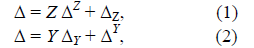
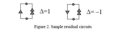
where ΔZ and ΔY are determinants of the circuit matrix when elements with impedance Z or conductance Y have been omitted, ΔZ and ΔY are determinants of the circuit matrix when these elements have been short circuited. Repeating eq.(1),(2) as recurrent formulas all elements corresponding to passive components of the circuit can be removed. After the removal the residual circuit will consist of a number of oriented nullors. The determinant of such circuit can be equal to 0 or ± 1. It can be used to determine the sign of the initial determinants. Simplest examples of the residual circuits consist of one oriented nullor are shown in Fig.2 [5]. Each pair of the nullator and norator should be numerated to avoid a possible error when the nullor
will be formed as a combination of the nullator and norator.
Generally speaking this approach is computation effective for the symbolic analysis of circuits based on idealized operational amplifiers (OpA’s) and can be considered as a particular case of the approach proposed in the current paper. Fig.3, where all types of controlled sources are depicted, illustrates an idea of the method [14].
The determinant of the circuit matrix is presented as a sum of two terms. The first term corresponds to the contribution of the active element and the second one corresponds to the contribution of the transformed part of the circuit when the controlled source is extracted from it. Depending on the type of controlled sources nodes connected with it should be shorted or opened. This statement can be reflected by the following equation in a generalized form

where parameter χ corresponds to the value of the controlled source parameter, Δ(χ →1) and Δ(χ →0) correspond to determinants of the circuit matrix when the controlled source is replaced by the oriented nullor and when the controlled source is deleted from the circuit respectively.
Taking into account a known transform of the passive branch to its presentation as a controlled source, it is possible to demonstrate that eq.(1),(2) are following from eq.(3).
To prove the equation (3), consider, as an example, the parameter extraction of the voltage controlled current source (VCCS) (see Fig.3, line 1). In the first step the input generator of the initial circuit is equivalently transformed to the VCCS (see Fig. 3, [8]). Using the result of [8] (see eq. (17), [8]), the determinant of the obtained circuit can be presented as
where Py and P0 correspond to nominator and denominator of the circuit transconductance. Taking into account the presentation of the network functions proposed in [4] (see Fig. 1, [4]) and the eq. (18) [8], the following equality can be written
A combination of the equations (4) and (5) gives the result Δ = y Δ(y→1) + Δ(y→0).
The extraction of the parameter of other controlled sources is discussed analogously.
Consider further the calculation of the first term in eq.(3). The determinant Δ(χ→1) is calculated using two procedures. The first one is passive component extraction by means of formulas (1) and (2). As it was mentioned in Introduction the residual circuit consists of a number of nullors. The procedure for the calculation of this residual circuit determinant formulated in [4] is based on incidence matrix presentation. Here we would like to propose an algorithm based on equivalent nullor circuit transformation. It doesn't require any special circuit presentation both in the matrix or graph forms [5]. Thus, let us consider the circuit consisting of a number of oriented nullors only. In general case the circuit can consist of a combination of oriented nullors, controlled sources and passive elements. The discussed procedure will later be called "nullor extraction" and can be formalized by the following steps
1. Choice of basic node. As the basic node only the node that is connected to singular elements can be chosen. Тhe basic node corresponds to the common node of nullator and norator of the extracted nullor.
2. The basic node is splitted to two nodes in order that the first of them will be connected with nullators only while the second node will be connected with norators only.
3. Branches corresponding to nullator and norator of the extracted nullor are short circuited.
The extraction of the nullor number n can be formalized by the following formula
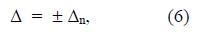
where Δn is the determinant of the circuit matrix after the procedure of the nullor number n extraction. Generally speaking this equation means that the nullor extraction will change the sign of the initial determinant. The choice of the sign depends on the orientation of the nullator and norator. If these elements have got the same orientation with respect to the basic node that the sign will be positive. In the opposite case the sign will be negative. To prove the equation (6), has been used the two-graph method.
The discussed approach has been realized in the program CIRSYM as a part of the software tool SYMBOL. The program can be downloaded from the site http://astrometric.sai.msu.ru/~symbol/. The program CIRSYM has been successfully used to form transfer functions of the test bandpass filter shown, for example, in the paper [1, Fig.15] and μA741 OpA. A sequence of expressions titled as "Filaretov2" and rewritten in the paper [14] describes the filter transfer function. The realized method has got the second position in the site http://www.eng.uts.edu.au/~benr/symbolic/ where the effectiveness of a number of symbolic algorithms has been discussed.
EXAMPLE
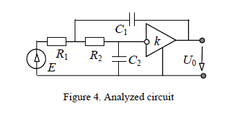
As an example consider the procedure of the symbolic analysis of the active filter shown in Fig.4
Let us express the filter transfer function as U0/E=ΔN/ΔD.
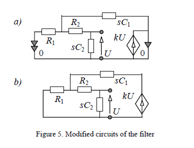
Equivalent circuits of the filter for the calculation of the transfer function numerator and denominator are shown in Fig.5 a,b. The additional nullor number 0 is introduced to the circuit to determine its numerator in accordance with [4].
The analysis procedure is presented as a number of steps of the transfer function calculation. It consists of the recurrent using of extraction operations (see eq.(1)–(3)) for passive elements, and dependent sources. The elements R1 and kU are extracted in accordance to eq.(1) and eq.(3) on the first step. The calculated numerator is shown in Fig.6.
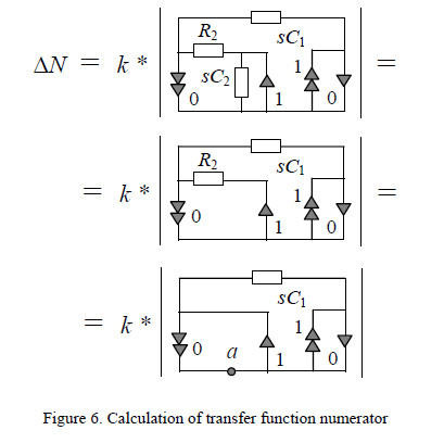
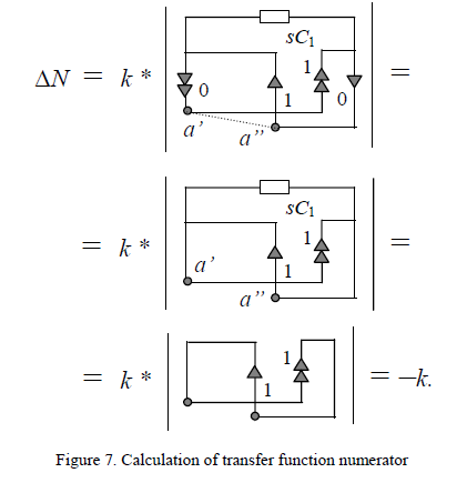
The extraction of the nullor number 0 can be done by the formula (6). For the nullor number 0 extraction (see Fig.6) the ground node numbered by a can be used as the basic node. On the second step this node is splitted to two nodes a’ and a”. To the first of them norators are only connected while all nullators are connected to the second node. Following the discussed algorithm, branches of the nullor number 0 are short circuited. This operation will not change the sign of the determinant because the orientation of norator and nullator of the extracted nullor was the same respect to the basic node. The elements sC1 are extracted in accordance to eq.(2). On the next step the determinant of the obtained circuit is calculated using Fig.2. Fig.7 illustrates these operations.
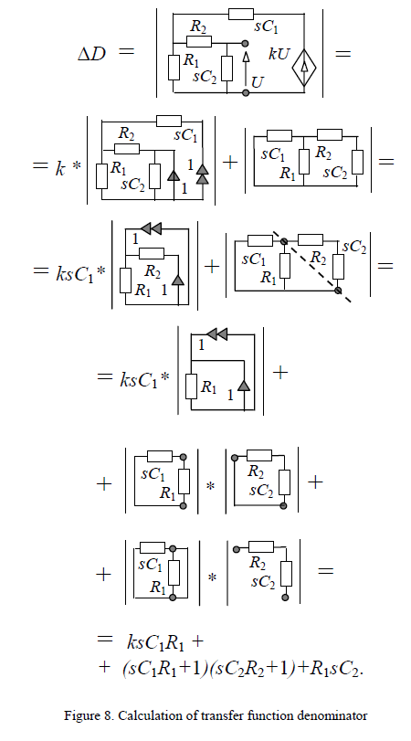
The same algorithm is applied to determine the transfer function denominator ΔD. The calculation of the denominator is illustrated by Fig.8. On the first step the extraction of the gain factor has been done. On the second step the second produced circuit is splitted to two subcircuits in accordance to [6] (see also papers [9] and [14]). On the third step determinants are calculated using the discussed procedures.
A combination of the equations in Fig.7 and Fig.8 gives the result U0/E=–k/[(sC1R1+1)(sC2R2+1)+R1sC2+ksC1R1].
|